Skip to main page content
U.S. flag

An official website of the United States government

Dot gov

The VSports app下载. gov means it’s official. Federal government websites often end in . gov or . mil. Before sharing sensitive information, make sure you’re on a federal government site. .

Https

The site is secure V体育官网. The https:// ensures that you are connecting to the official website and that any information you provide is encrypted and transmitted securely. .

. 2011 Sep 13;108(37):15342-7.
doi: 10.1073/pnas.1105316108. Epub 2011 Aug 29.

Fluid forces control endothelial sprouting

Affiliations

VSports注册入口 - Fluid forces control endothelial sprouting

"V体育ios版" Jonathan W Song et al. Proc Natl Acad Sci U S A. .

Abstract

During angiogenesis, endothelial cells (ECs) from intact blood vessels quickly infiltrate avascular regions via vascular sprouting. This process is fundamental to many normal and pathological processes such as wound healing and tumor growth, but its initiation and control are poorly understood. Vascular endothelial cell growth factor (VEGF) can promote vessel dilation and angiogenic sprouting, but given the complex nature of vascular morphogenesis, additional signals are likely necessary to determine, for example, which vessel segments sprout, which dilate, and which remain quiescent. Fluid forces exerted by blood and plasma are prime candidates that might codirect these processes, but it is not known whether VEGF cooperates with mechanical fluid forces to mediate angiogenesis. Using a microfluidic tissue analog of angiogenic sprouting, we found that fluid shear stress, such as exerted by flowing blood, attenuates EC sprouting in a nitric oxide-dependent manner and that interstitial flow, such as produced by extravasating plasma, directs endothelial morphogenesis and sprout formation VSports手机版. Furthermore, positive VEGF gradients initiated sprouting but negative gradients inhibited sprouting, promoting instead sheet-like migration analogous to vessel dilation. These results suggest that ECs integrate signals from fluid forces and local VEGF gradients to achieve such varied goals as vessel dilation and sprouting. .


Conflict of interest statement

The authors declare no conflict of interest.

VSports注册入口 - Figures

Fig. 1.
Fig. 1.
Microfluidic device with localized 3D ECM for fluid force-mediated angiogenic sprouting and morphogenesis. (A) Multilayer fabrication of the poly(dimethylsiloxane) PDMS microfluidic device featuring localized region of collagen gel (blue). The top PDMS layer contains the channel features (50 μm in height) and the bottom layer provides a planar surface. (B) HUVECs seeded into two channels separated by multiple collagen gel apertures visualized under phase microscopy. (C) Immunofluorescence staining for VE-cadherin expression (red) demonstrates integrity at intercellular junctions of the HUVEC monolayer. Blue depicts nuclei stained with DAPI. (D) Cross-section view of one of the HUVEC channels. HUVEC-GFP cells seeded on top, bottom, and Side faces mimicking a fully-lined blood vessel. (E) HUVEC-GFP cells sprouting into 3D collagen gel demonstrate clear morphological differences, with HUVECs invading the bulk of the gel rather than along the top or bottom surface. (F) Close-up view of boxed area in A showing seven apertures that allow connection of the two HUVEC channels (green) through the collagen barrier (blue). Each HUVEC channel has independent input and outlet ports, allowing strict control over flow in both channels (SA and SB) and across the collagen matrix (T). As drawn, the nomenclature for this flow configuration is SA3TwG|SB0TaG+. (Scale bars, 100 μm.)
Fig. 2.
Fig. 2.
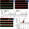
Shear stress attenuates VEGF-induced HUVEC invasion. (A) To examine the role of shear stress, identical flow (3 dyn cm−2) and VEGF conditions (50 ng mL−1) were applied to the Upper and Lower channels (SA3T0G0|SB3T0G0|V50), resulting in no interstitial flow or VEGF gradient across the collagen gel (see Table 1 for explanation of nomenclature). Invasion was minimal from both channels. (B) Without flow, application of 50 ng mL−1 VEGF-containing media in both HUVEC channels under static conditions results in dramatic invasion (SA0T0G0|SB0T0G0|V50 configuration). Solid blue VEGF bar indicates uniform VEGF concentration in the collagen gel. (C) Normalized area of invasion in the 3D collagen gel from sheared (SA3T0G0|SB3T0G0) and static (SA0T0G0|SB0T0G0) channels with various VEGF concentrations. (D) In the SA3T0G0|SB3T0G0|V50 flow configuration, the pan-NOS inhibitor L-NMMA was added to the medium in the Upper channel (SA3T0G0|L) resulting in significant invasion. (E) Normalized area of invasion in the 3D collagen gel for the flow configuration in D. Under shear flow, HUVEC invasion requires both VEGF stimulation and NO inhibition by L-NMMA. Duration of all experiments was 3 d. Data points on the graphs represent mean values and error bars depict SEM. Sample populations were compared using two-way ANOVA (row factor was day of treatment; column factor was treatment condition). Statistical outcome indicated for treatment condition (e.g., SA0T0G0|V50 vs. SA3T0G0|V50). n = 21–28 per condition per day. ***P < 0.0001; ns, P = 0.33. Images represent a mosaic of 4 separate 10× fields acquired along the length of the device, spliced together automatically using the Photomerge command in Adobe Photoshop (SI Materials and Methods, Image Acquisition and Processing). (Scale bars, 100 μm.)
Fig. 3.
Fig. 3.
Shear stress attenuates HUVEC invasion irrespective of the direction of interstitial flow and VEGF gradient. (A) In the flow configuration SA3TaG+|SB0TwG|V50, positive pressure shear flow (3 dyn cm−2) in channel A (Upper) results in interstitial flow of 50 ng mL−1 VEGF-containing medium at a rate of 2.5 μm s−1 and a VEGF gradient from channel A to channel B (Lower). (B) In the flow configuration SA0TwG|SB3TaG+|V50, negative pressure shear flow (3 dyn cm−2) in channel B results in interstitial flow at a rate of 35 μm s-1 and a VEGF gradient from A to B. Solid arrows indicate direction of axial flow in the HUVEC channels; dashed arrows indicate direction of interstitial flow. Blue gradient bar indicates VEGF gradient from A to B in the collagen gel. Images represent a mosaic of four separate 10× fields acquired along the length of the device, spliced together automatically using the Photomerge command in Adobe Photoshop (SI Materials and Methods, Image Acquisition and Processing). (Scale bars, 100 μm.) (C) Normalized area of invasion in the 3D collagen gel for the SA3TaG0|SB0TwG0|V0, SA3TaG+|SB0TwG|V5, and SA3TaG+|SB0TwG|V50 flow configurations. (D) Normalized area of invasion in 3D collagen space for the SA0TwG0|SB3TaG0|V0, SA0TwG|SB3TaG+|V5, and SA0TwG|SB3TaG+|V50 flow configurations. HUVEC invasion occurs mainly from the nonsheared channels and irrespective of the direction of interstitial flow and VEGF gradients in channels A and B. Duration of all experiments was 3 d. Data points represent mean + SEM. Statistical outcome indicated for treatment condition (V0 vs. V5 vs. V50). n = 21–35 per day per condition. ***P < 0.0001; ns, P > 0.44.
Fig. 4.
Fig. 4.
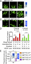
Sprout morphogenesis is affected by the direction of interstitial flow and VEGF gradient. (AC) Filopodia formation in sprouting HUVECs in the (A) SB0TaG+|V50, (B) SA0TwG|V50, and (C) SA0TwG0|SA0TwG0|V50 flow configurations. Interstitial flow rates were (A) 2.5, (B) 35, and (C) 28.5 μm/s. Each image depicts a single aperture imaged 2–3 d after initiation of experiment. (Scale bars, 100 μm.) (D) Quantification of the number of filopodia per sprouting area produced by sprouting HUVECs. n = 5–21. *P < 0.05; **P < 0.001; ns, P = 0.96. Gradient blue and solid blue VEGF bars indicate VEGF gradient and uniform VEGF concentration, respectively, in the collagen gel. Dashed arrows indicated direction of interstitial flow. (E) Isolated effects of interstitial flow and VEGF gradient on sprouting area, comparing the normalized sprout area at day 3 from each sprouting direction (with interstitial flow and a negative VEGF gradient or against interstitial flow with a positive VEGF gradient). Interstitial flow alone significantly enhances sprout area for both sprouting directions (***). Addition of a VEGF gradient to interstitial flow significantly increases sprout area compared with interstitial flow only, for both sprouting directions (***′). Furthermore, the normalized area of sprouting for interstitial flow only (B→A: 39 ± 5; A→B: 37 ± 6) plus VEGF gradient only (B→A: 28 ± 5; A→B: 23 ± 4) is comparable to the area when both VEGF gradient and interstitial flow are present (B→A: 65 ± 10; A→B: 56 ± 7), suggesting that these components are additive in enhancing sprout area for both sprouting directions. n = 21–49. Data points represent mean + SEM. *** or ***′P < 0.0001.
Fig. 5.
Fig. 5.
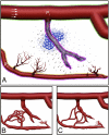
Putative integration of flow forces and VEGF in damaged tissue. (A) Hypoxic cells (blue) residing in an ischemic region produce VEGF (small blue dots). The damaged, occluded vessel within this region lacks shear stress, but fills with VEGF, and its ECs sense a negative VEGF gradient. This vessel dilates (walls outlined in pink) and becomes leaky in response (arrows; note that P1 > P2). Proximal ECs in the other occluded vessel (Lower) see a positive VEGF gradient across the vessel wall (orange outline), whereas those in the opposite wall see a negative gradient (pink outline). The former sprout, whereas the latter dilate. Morphogenesis of nondamaged, well-perfused vessels is inhibited by shear stress (green outline). (B and C) Interstitial flow supports efficient revascularization. If no fluid forces were involved with mediating revascularization and instead relied solely on VEGF and other chemical factors, then many self-connections would be made between the sprouting vessels, leading to inefficient reperfusion (B). However, interstitial flow originating from the leaky and dilated central vessel serves as an important cue that guides the sprouts toward this higher-pressure vessel to ensure more uniform revascularization of the central region (C).

References

    1. Carmeliet P, Jain RK. Angiogenesis in cancer and other diseases. Nature. 2000;407:249–257. - PubMed
    1. Davis GE, Bayless KJ, Mavila A. Molecular basis of endothelial cell morphogenesis in three-dimensional extracellular matrices. Anat Rec. 2002;268:252–275. - PubMed
    1. Ingber DE. Mechanical signaling and the cellular response to extracellular matrix in angiogenesis and cardiovascular physiology. Circ Res. 2002;91:877–887. - PubMed
    1. Carmeliet P, De Smet F, Loges S, Mazzone M. Branching morphogenesis and antiangiogenesis candidates: Tip cells lead the way. Nat Rev Clin Oncol. 2009;6:315–326. - PubMed
    1. Gerhardt H, et al. VEGF guides angiogenic sprouting utilizing endothelial tip cell filopodia. J Cell Biol. 2003;161:1163–1177. - PMC - PubMed

Publication types

MeSH terms

Substances (V体育2025版)